Design Digital Speedometer


This instrument displays the speed of the vehicle in( kmph). In the design of speedometer,vehicle wheel are in circular.Hence in the design consideration.Rotational motion have to be sensed(in terms of linear) and i.e distance.Selection of approriate sensor,and design have the fallowing stages
i) sensor and transducer
ii) astable multivibrator
iii) digital counter
mechanical arrangment:

phototransistor
Transducer design:
A device used to convert ,or sensed on form of signal to electic signal of standard voltage range. Signal sensed from sensor is electic signal of voltage range may varying between 0-5 V.
when high may be less than exact 5v,signal is converted to standard 5V or 0 V.It is done using comparator LM324 ,Which is a transducer.


design consideration of counter unit:
Converted signed 0-5V is counted using 7490 decade counter. Its counted for particular time using gating signal.

timing consideration:

using the 74175 the counter data stored in 74175 is refreshed. Using 7447 driver ic data is converted 7-sigment code.
 ,
,
Detailed design :
An opaque disc is mounted on the spindle attached to the front wheel of the vehicle. The disc has ten equidistant holes on its periphery. On one side of the disc an infrared LED is fixed and on the opposite side of the disc in line with the IR LED, a phototransistor is mounted. IC LM324 is wired as a comparator. When a hole appears between the IR LED and phototransistor, the phototransistor conducts. Hence the voltage at collector of the phototransistor and inverting input of LM324 go ‘low’, and thus output of LM324 becomes logic ‘high’. So rotation of the speedometer cable results in a pulse (square wave) at the output of LM324. The frequency of this waveform is proportional to the speed. Let ‘N’ be the number of pulses in time ‘t’ seconds and numerically equal to the number of kilometres per hour (kmph). For a vehicle such as LML Vespa, with a wheel circumference of 1.38 metres, and number of pulses equal to 10 per revolution,
we get the relationship:
calculation for design,and gating pulses:
N pulses / t = N kmph = (Nx1000)/(3600x1.38) metres per second
= (Nx1000x10)/(3600x1.38)
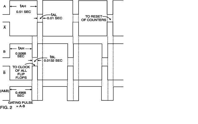
pulses per second Therefore, time ‘t’ in seconds = 0.4968 second. As shown in the timing diagram, at t=0, output of astable timer 1 i.e. 555 goes low and triggers monostable multivibrator IC1(b) i.e. 555. Pulse width of monostable IC1(b) = 0.5068 sec. For IC1(a), t(on) = 0.51 sec. and t(off)= 0.01 sec. The outputs of IC1(a) and IC1(b), and the signal from the transducer section are ANDed.
The number of pulses counted during the gating period(0.4968 sec.) is the speed N in kmph (kilometres per hour). At the end of the gating period,output ‘B’ of monostable IC1(b) goes low and B goes high. The rising edge of B is used to enable the quad ‘D’ flip-flops IC6 and IC7. At this instant, i.e. at t=0.5068 sec., the number (speed) N will be latched corresponding to the ‘D’ flip-flops and displayed. At t=0.52 sec., output of astable 555 timer IC1(a) goes low and remains low for 0.01 sec. This waveform is inverted and applied to the reset terminals of all counters (active high). Thus the counters are reset and counting begins afresh at t=0.53 sec. up to the time t=0.52+0.2068 sec. However the ‘D’ flip-flops are not enabled and the previous speed is displayed. The new speed is displayed at t=0.52 + 0.5068 sec. In this way the speed will be updated every 0.52 sec. This speedometer can measure up to 99 kmph with a resolution of 1 kmph. Basic digital counter:

The range can be increased up to 999 kmph by adding another stage consisting of one each of ICs 7490, 74175, 7447 and a 7-segment display. The voltage supply required for the operation of the circuit is derived from the vehicle power supply (12V). The calculations shown above are for LML Vespa and Kinetic Honda. The calculations for using this speedometer for Yamaha, whose circumference of wheel = 1.8353m, can be obtained in a similar fashion. The gating period will simply vary in direct proportion to the wheel diameter. It will be 0.6607 sec. for Yamaha.
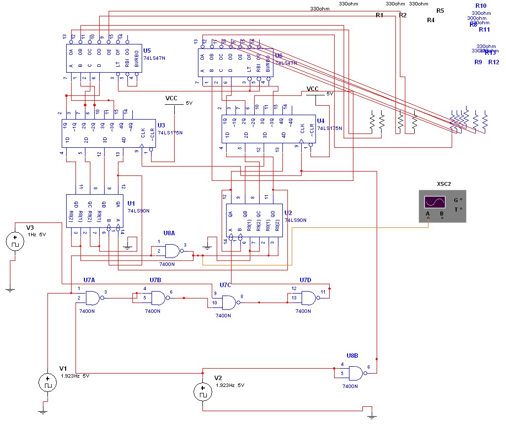
design on of circuit on multisim(ni work bench):

The same speedometer can be used for other vehicles by making similar calculations. In all the calculations it has been assumed that the speedometer cable makes one revolution for every revolution of the wheel of the vehicles. Note that on/off periods of the wave-forms have to be precise. High quality multiturn pots and low temperature coefficient components should be used in the timer ICs.
desiged speedometer-


This instrument displays the speed of the vehicle in( kmph). In the design of speedometer,vehicle wheel are in circular.Hence in the design consideration.Rotational motion have to be sensed(in terms of linear) and i.e distance.Selection of approriate sensor,and design have the fallowing stages
i) sensor and transducer
ii) astable multivibrator
iii) digital counter
mechanical arrangment:

phototransistor
Transducer design:
A device used to convert ,or sensed on form of signal to electic signal of standard voltage range. Signal sensed from sensor is electic signal of voltage range may varying between 0-5 V.
when high may be less than exact 5v,signal is converted to standard 5V or 0 V.It is done using comparator LM324 ,Which is a transducer.


design consideration of counter unit:
Converted signed 0-5V is counted using 7490 decade counter. Its counted for particular time using gating signal.

timing consideration:
using the 74175 the counter data stored in 74175 is refreshed. Using 7447 driver ic data is converted 7-sigment code.
 ,
, Detailed design :
An opaque disc is mounted on the spindle attached to the front wheel of the vehicle. The disc has ten equidistant holes on its periphery. On one side of the disc an infrared LED is fixed and on the opposite side of the disc in line with the IR LED, a phototransistor is mounted. IC LM324 is wired as a comparator. When a hole appears between the IR LED and phototransistor, the phototransistor conducts. Hence the voltage at collector of the phototransistor and inverting input of LM324 go ‘low’, and thus output of LM324 becomes logic ‘high’. So rotation of the speedometer cable results in a pulse (square wave) at the output of LM324. The frequency of this waveform is proportional to the speed. Let ‘N’ be the number of pulses in time ‘t’ seconds and numerically equal to the number of kilometres per hour (kmph). For a vehicle such as LML Vespa, with a wheel circumference of 1.38 metres, and number of pulses equal to 10 per revolution,
we get the relationship:
calculation for design,and gating pulses:
N pulses / t = N kmph = (Nx1000)/(3600x1.38) metres per second
= (Nx1000x10)/(3600x1.38)
pulses per second Therefore, time ‘t’ in seconds = 0.4968 second. As shown in the timing diagram, at t=0, output of astable timer 1 i.e. 555 goes low and triggers monostable multivibrator IC1(b) i.e. 555. Pulse width of monostable IC1(b) = 0.5068 sec. For IC1(a), t(on) = 0.51 sec. and t(off)= 0.01 sec. The outputs of IC1(a) and IC1(b), and the signal from the transducer section are ANDed.
The number of pulses counted during the gating period(0.4968 sec.) is the speed N in kmph (kilometres per hour). At the end of the gating period,output ‘B’ of monostable IC1(b) goes low and B goes high. The rising edge of B is used to enable the quad ‘D’ flip-flops IC6 and IC7. At this instant, i.e. at t=0.5068 sec., the number (speed) N will be latched corresponding to the ‘D’ flip-flops and displayed. At t=0.52 sec., output of astable 555 timer IC1(a) goes low and remains low for 0.01 sec. This waveform is inverted and applied to the reset terminals of all counters (active high). Thus the counters are reset and counting begins afresh at t=0.53 sec. up to the time t=0.52+0.2068 sec. However the ‘D’ flip-flops are not enabled and the previous speed is displayed. The new speed is displayed at t=0.52 + 0.5068 sec. In this way the speed will be updated every 0.52 sec. This speedometer can measure up to 99 kmph with a resolution of 1 kmph. Basic digital counter:

The range can be increased up to 999 kmph by adding another stage consisting of one each of ICs 7490, 74175, 7447 and a 7-segment display. The voltage supply required for the operation of the circuit is derived from the vehicle power supply (12V). The calculations shown above are for LML Vespa and Kinetic Honda. The calculations for using this speedometer for Yamaha, whose circumference of wheel = 1.8353m, can be obtained in a similar fashion. The gating period will simply vary in direct proportion to the wheel diameter. It will be 0.6607 sec. for Yamaha.
design on of circuit on multisim(ni work bench):
The same speedometer can be used for other vehicles by making similar calculations. In all the calculations it has been assumed that the speedometer cable makes one revolution for every revolution of the wheel of the vehicles. Note that on/off periods of the wave-forms have to be precise. High quality multiturn pots and low temperature coefficient components should be used in the timer ICs.
desiged speedometer-

